目标
Upon completion of this module, you should be able to:
Use Tessent Scan to insert full scan. Write a scan-inserted netlist file. Write ATPG setup files. lnsert test logic. Create, configure, and balance scan chains. Edit a scan chain order file and change the order of the scan cells.
完成这个模块后,您应该能够:
· 使用Tessent Scan插入完整的扫描。
· 编写插入扫描的网表文件。
· 编写ATPG设置文件。
· 插入测试逻辑。
· 创建、配置和平衡扫描链。
· 编辑扫描链顺序文件并更改扫描单元的顺序。
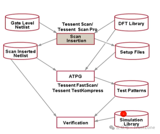
Tessent Scan Tool Flow: An Overview
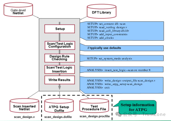
Tessent Scan Tool Flow With Commands
DFT Library
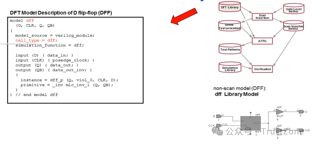 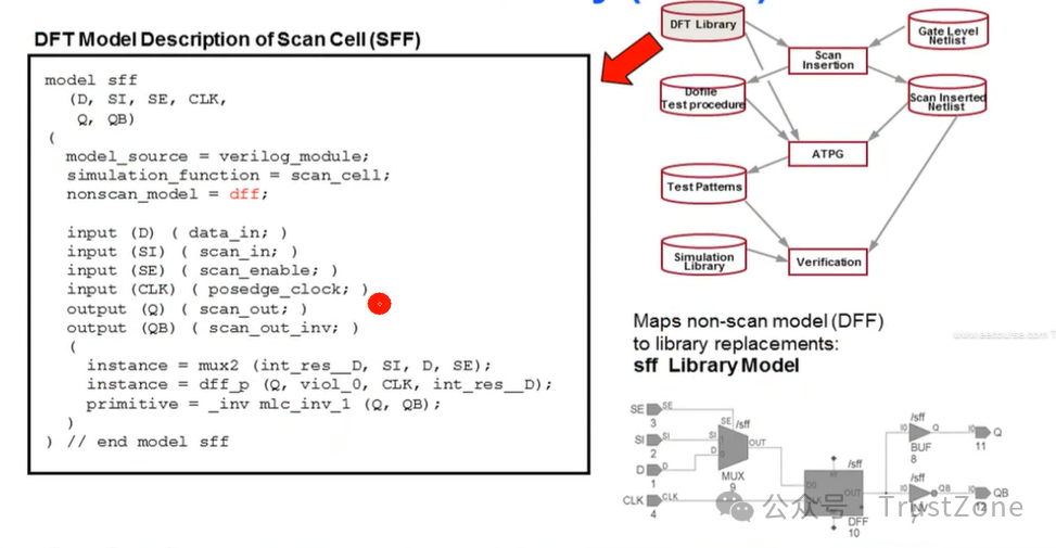
The DFT library is a function of the lowest level netlist modules.
Very similar to Verilog.
Maps non-scan models to their associated scan models.
No DFT model is needed for Verilog primitives.
Example:Verilog “and" maps directly to the built-in primitive “and" in DFT tools.
DFT库是最低级别网表模块的函数。
· 与Verilog非常相似。
· 将非扫描模型映射到其相关的扫描模型。
· 对于Verilog原语,不需要DFT模型。
示例:Verilog中的“and”直接映射到DFT工具中的内置原语“and”。
Creating a DFT Library
Check for an existing library from the vendor.
Use the libcomp utility to make a DFT library from Verilog..
libcomp is a shell conhimand.
Technical marketing or support will help with any library conversion issues.
检查供应商是否已有现成的库。
使用libcomp工具从Verilog生成DFT库。
libcomp是一个shell命令。
技术营销或支持部门将协助解决任何库转换问题。
Automatic Generation of DFT Libraries
Automatically converts Verilog simulation library.
· Translates and optimizes UDPs
· Automated verification of translated models.
· Reports coverage per model
· Reduces the effort in creating an ATPG library
自动转换Verilog仿真库。
· 翻译并优化UDP(用户定义原语)
· 自动验证翻译后的模型
· 按模型报告覆盖率
· 减少创建ATPG(自动测试模式生成)库的工作量
SETUP: Scan Cell Mapping
Default:
Mapping nonScan to Scan cells is defined in the DFT library
Options:
set_cell_mapping <....….> -output qb
set_cell_mapping -new_model-model.
Override the scan cell mappings using
Override default output pino
Output pins
Scan Insertion will select the pin with the smaller fanout to use as the scan_out of the inserted scan cell.
默认设置:
在DFT库中定义了非扫描单元到扫描单元的映射
选项:
set_cell_mapping <....….> -output qb
set_cell_mapping -new_model <newScanModel> -model <modelName>。
使用以下命令覆盖扫描单元映射:
覆盖默认的输出引脚
输出引脚:
扫描插入会选择具有较小扇出的引脚作为插入的扫描单元的scan_out。
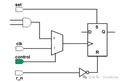
SETUP: Input Constraints
· lnput constraints define initial conditions of primary inputs as the design is put into testsetup
· The pin will be held at that value until it is changed via a procedure defined in the testprocedure file.
add_input_constraints control -c1
· 输入约束定义了当设计进入测试设置时主要输入的初始条件
· 该引脚将保持该值,直到通过测试过程文件中定义的过程将其更改。
SETUP: Adding Clocks
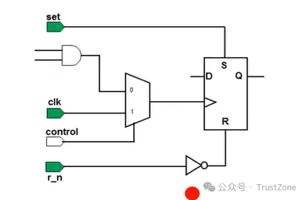
· In order to define scan chains, the appropriate clocks must be defined.
· The command analyze_control_signals will automatically identify clocks, set, resetthat connect to sequential elements.
· Manually, you can issue the command
add_clocks 0 CLK1 || 0 = offstate, CLK1 net name
· 为了定义扫描链,必须定义相应的时钟。
· 命令analyze_control_signals会自动识别连接到顺序元素的时钟、设置和复位信号。
· 手动地,您可以发出命令
add_clocks 0 CLK1 || 0表示关闭状态,CLK1是网络的名称
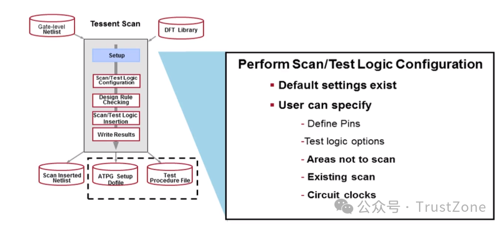
SETUP:Scan/Test Logic Configuration
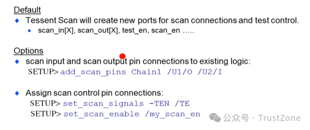
SETUP: Defining Pin Connections
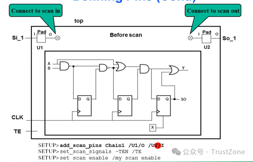 
SETUP: Adding Test Logic
Why do we add test logic?
· Some designs contain uncontrollable clock circuitry.
· Sequential devices must be controllable to be converted to scan.
· RAM and three-state logic must be controllable to be testable.
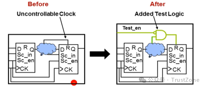
一些设计中包含不可控制的时钟电路。

为了使电路可扫描,添加了测试逻辑。

为了添加测试逻辑电路,Tessent Scan 从 ATPG 库中使用了一些组合门电路。例如:
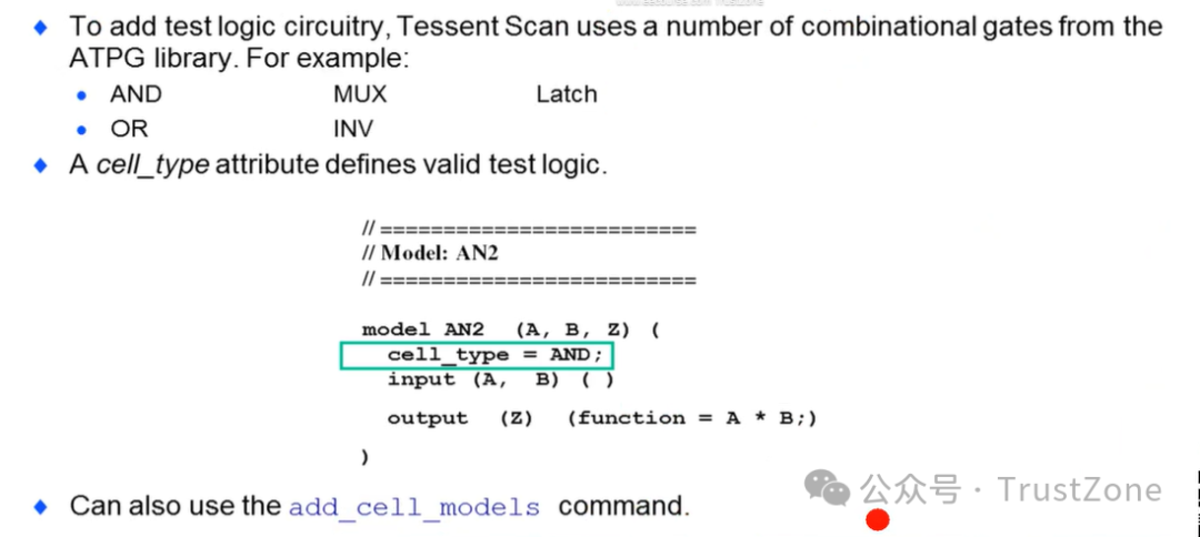
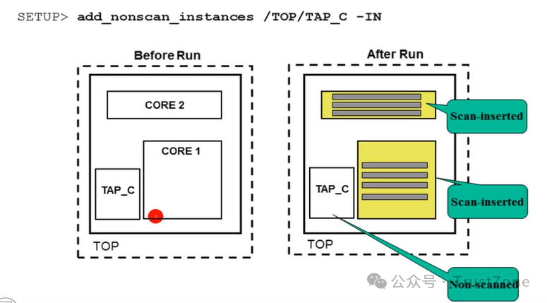
SETUP: Set Test Logic Configuration (Defining Non-Scan Areas)
将TAP控制器排除在扫描之外
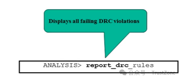
SETUP: Design Rule Checking (DRC)
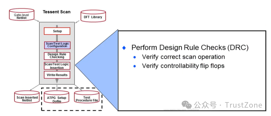
SETUP: Scan Specific DRCs
General rules (G rules)
Checks for general scan definition errors
Trace rules (T rules)
Bus contention or data shifted through scan chains
Uses test procedure files to trace scan chains
Scannability rules (S rules)
s1 rule checking: Ensures that all clocks off-sequential elements are stable and inactive
s2 rule checking Ensure that defined clocks capture data when all other clocks are off
Ensures that Tessent Scan can safely convert a sequential element into a scan element
Checks scannability during DRC
通用规则(G规则)
检查一般的扫描定义错误
追踪规则(T规则)
总线争用或数据通过扫描链移位
使用测试过程文件来追踪扫描链
可扫描性规则(S规则)
s1规则检查:确保所有非顺序元素的时钟都是稳定的且不活动的
s2规则检查 确保定义的时钟在所有其他时钟关闭时捕获数据
确保Tessent Scan可以安全地将顺序元素转换为扫描元素
在DRC期间检查可扫描性
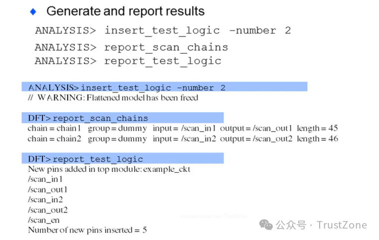
ANALYSIS: Scan/Test Logic lnsertion

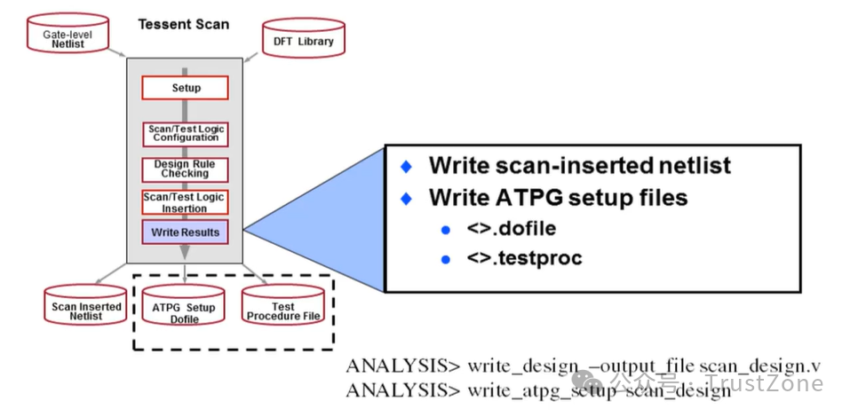
ANALYSIS: Saving Scan Inserted Design
Additional Topics
Leading Edge / Trailing Edge Scan Cells
One chain, 2 clocks
Balancing Scan Chains
Scan Chain Ordering and Stitching
上升沿/下降沿扫描单元
一条扫描链,两个时钟
平衡扫描链
扫描链排序和拼接
Leading Edge / Training Edge Scan Cells
默认情况下,所有的时钟主要输入和边沿都被放置在单独的扫描链中。
ANALYSIS> insert_test_logic
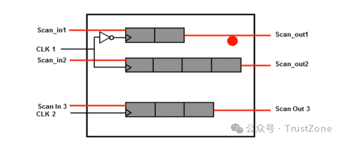
Leading and trailing edge clocks can be combined into the same scan chain.
Tessent Scan groups all trailing edge clock scan cells first
上升沿和下降沿时钟可以合并到同一个扫描链中。
Tessent Scan 首先将所有下降沿时钟扫描单元组合在一起。
ANALYSIS> insert__test_logic-edge merge
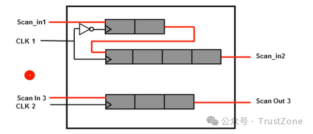
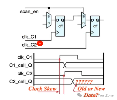
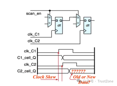
One Chain -2 Clocks
There is a chance that clock skew will cause timing issues when a single scan chaindriven from 2 clock domains
当单个扫描链由两个时钟域驱动时,存在时钟偏移可能导致时序问题的情况。
By default, Tessent Scan will add a lockup latch at the transition of the two clock domainswill eliminate skew issues.
默认情况下,Tessent Scan 会在两个时钟域的转换处添加一个锁定锁存器,以消除时钟偏移问题。
ANALYSIS> insert_test_logic -clock merge
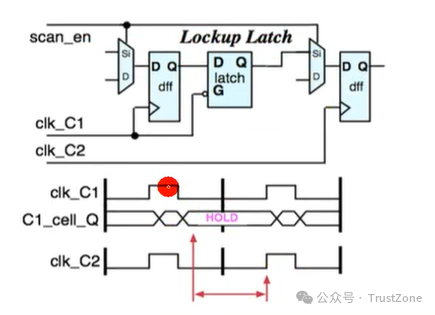
当单个扫描链由两个时钟域驱动时,存在时钟偏移导致时序问题的可能性。
Balancing Scan Chains
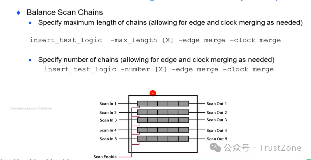
Testers need deep serial memory for every scan input and output pin.
Functional pins can be shared as scan pins in test mode.
Test time and cost is reduced with more and shorter scan chains.
The number of scan chains is dependent upon tester capabilities.
测试器需要为每个扫描输入和输出引脚提供深串行存储器。
在测试模式下,功能引脚可以作为扫描引脚共享。
扫描链越多且越短,测试时间和成本就越低。
扫描链的数量取决于测试器的能力。

Balance scan chains by defining:
Maximum length
or by setting their total number.
通过定义以下内容来平衡扫描链:
最大长度
或设置它们的总数。
Lab1:Configuring Scan Chain/Test Logic
During this lab ,you will
· Configure scan chains and insert test logic in a full scan flow
· Set up scan pins
· Balance scan chains with multiple domains
· Stitch scan chains
在本次实验中,您将
· 配置扫描链并在全扫描流程中插入测试逻辑
· 设置扫描引脚
· 使用多个域来平衡扫描链
· 拼接扫描链
只有把Scan做好,才能做ATPG
碍于时间,很多点并未展开聊聊。以上内容都来自最近我在看的一个课程:
点击这里:E课网IC设计学习卡
课程以IC设计公司岗位需求为导向,设立6大方向:设计,验证,后端,DFT,模拟设计,版图!同时还有芯片设计全流程的通用基础入门课!
课程内容配套持续优化:PPT课件、实验手册、作业练习!有需要的同学,同时还可配套VNC账号,理论学习+实操环境数据一次解锁!
拥有了学习卡,不仅可以快速掌握芯片设计的基础通识,还能判断自己是不是适合做芯片设计的工作,单门课程花几天的时间就可以学完,极大提升学习效率!
|


