目标
完成本文的阅读后,您应该能够:
· Describe the difference between engineering test and manufacturing test.
· Explain what scan test is.
· Describe the basic scan test process.Explain what manufacturing defects are.
· List the common fault models used in test.
· Explain why test patterns are created.lnvoke ATPG tools inside of Tessent Shell.
· Use commands to access online help and documentation.
· 描述工程测试与制造测试之间的区别。
· 解释扫描测试是什么。
· 描述基本的扫描测试过程。
· 解释什么是制造缺陷。
· 列出测试中常用的故障模型。
· 解释为何需要创建测试模式。
· 在Tessent Shell中调用ATPG工具。
· 使用命令访问在线帮助和文档。
为什么需要测试?
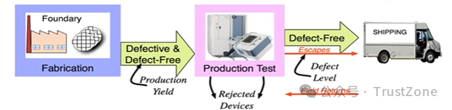
· Devices from foundry require testing to sort out the defective devices. Production testing applies test patterns to exercise devices for defect detection. Defect free devices are candidates for shipping to customers.
· Sometimes devices with a defect will pass all applied tests—these are known asescapes.
· Devices that fail at the customer site are returned.
· 从晶圆代工厂生产的设备需要进行测试以筛选出有缺陷的设备。
· 生产测试通过应用测试模式来测试设备以检测缺陷。无缺陷的设备是发送给客户的候选品。
· 有时带有缺陷的设备会通过所有应用的测试——这些被称为漏检。
· 在客户现场出现故障的设备会被退回。
测试类型
Functional/engineering tests
· Verify circuit functionality
Simulation,verification of design logic
Analog,digital,and mixed-signal testing
Can be board, subsystem, system, prototype, and so on
· lncludes pin parametrics
· Placing part into test mode
验证电路功能
· 仿真,设计逻辑验证
· 模拟、数字和混合信号测试
可以是板级、子系统、系统、原型等
· 包括引脚参数
· 将部件置于测试模式
制造测试
· Verifies that the design has no manufacturing defects.
· Does not verify the silicon behaves as specified.
The circuit may pass test, but the design may not be functionally correct (For example,may not operate as described in the functional spec.)
Types of manufacturing test
· Scan test: (Subject of this training).
· Scan test with compression (Subject of TessentTestKompress and Advanced Topics training course).[EDP]
BIST - Memory test (Subject of Tessent Memory BIST training course). - Logic test(Subject of TessentMemory BlST and Logic BlST training course).
Functional test
· Not as efficient as scan.
· Difficult to determine test coverage.
+ 验证设计没有制造缺陷。
+ 不验证硅片是否按规格运行。
>电路可能通过测试,但设计在功能上可能不正确(例如,可能无法按照功能规格描述的方式工作)。
**制造测试的类型**
+ 扫描测试:(本培训的主题)。
+ 带有压缩的扫描测试(TessentTestKompress和为文章的主题)。
+ BIST(内建自测试)
存储器测试(Tessent Memory BIST文章的主题)。
逻辑测试(Tessent Memory BIST和Logic BIST文章的主题)。
+ 功能测试
不如扫描测试高效。
难以确定测试覆盖率。
是什么测试?
Test is a control and observation problem
· Control:Can we intentionally stimulate the target site (gate inputloutput, path, and so on) with atest pattern?
· Can we observe the effect of the stimulation?
可观测,可控制
测试是一个控制和观察的问题
+ 控制:我们能否有意地使用一个测试模式来刺激目标位置(门输入/输出、路径等)?
+ 观察:我们能否观察到这种刺激的效果?
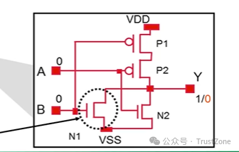
制造缺陷
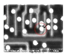
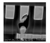
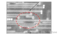
Manufacturing issues can cause various defects to show up in parts.For example:
Hard tie to power or ground:
Port is always stuck-at 1 or stuck-at o.
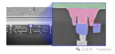
Shorts, or bridges between two connections:
Port is always stuck-at 1 or stuck-at 0.
Data in one path adversely effects data in a different path.
Capacitive or resistive pads:
lndividual ports may be slow during 0 -> 1 transition.
lndividual ports may be slow during 1 -> 0 transition.
Path delay could be longer than expected.
制造问题可能导致部件出现各种缺陷。例如:
+ 硬连接到电源或地线:
+ 端口始终保持在1或保持在0。
+ 两个连接之间的短路或桥接:
+ 端口始终保持在1或保持在0。
+ 一条路径中的数据会对另一条路径中的数据产生不利影响。
+ 电容性或电阻性焊盘:
+ 在0->1转换期间,单个端口可能较慢。
+ 在1->0转换期间,单个端口可能较慢。
+ 路径延迟可能比预期要长。
故障模型
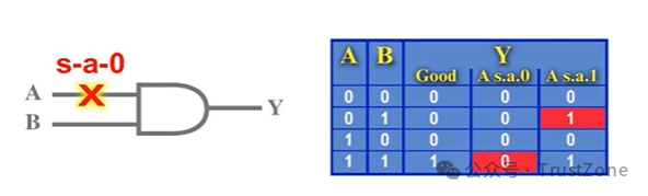
· Fault models provide a mechanism to emulate defects so test patterns can be generate dto identify the defects.
· A fault is detected when there is an observed difference between good behavior and faulty behavior.
· The most common fault model is a stuck-atfault model.
故障模型
故障模型提供了一种机制来模拟缺陷,以便生成测试模式来识别这些缺陷。
当观察到正常行为与故障行为之间存在差异时,即检测到故障。
最常见的故障模型是固定型故障模型。
故障模型和测试模式
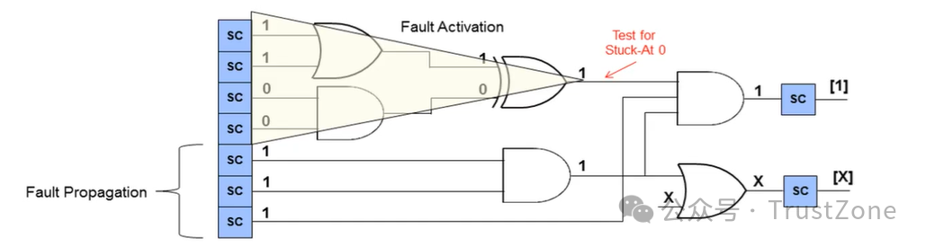
· Test Patterns accomplish 2 things: fault activation(control) and fault propagation (observe).
· Fault activation establishes a signal value at the fault model site that is opposite of the valueproduced by the fault model.
Example: lf testing for stuck-at 0(S-A-0),activation places a 1 at the site.
· Fault propagation moves the resulting signal value, or fault effect, forward by sensitizing apath from the fault site to a primary output or scan cell.
测试模式实现了两件事:故障激活(控制)和故障传播(观察)。故障激活是在故障模型的位置建立一个与故障模型产生的值相反的信号值。
例如:如果测试的是固定为0(S-A-0)的故障,激活会在该位置放置一个1。
故障传播通过使从故障位置到主输出或扫描单元的路径敏感化,将产生的信号值或故障效应向前传播。
Automatic Test Pattern Generation(ATPG)
Scan是基础
· A test cube are the defined states needed to control and observe a fault site.
· All X-states in control side are random fill.
· All ×-states in observation are masked during unload.
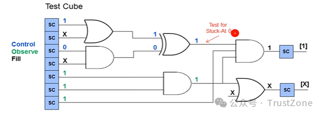
一个测试立方体是控制并观察一个故障位点所需的定义状态。
控制侧的所有X状态都是随机填充的。
在卸载时,观察侧的所有X状态都会被屏蔽。
The basic flow of the ATPG process is to select faultsfrom the user-selected fault set.
A pattern is created to control and observe the fault.
The pattern is fault simulated to determine if there is adifference between good and faulty machine simulations.
lf the targeted fault is detected the pattern is kept.
lf other faults also are fortuitously detected, thesefaults are also classified as detected.
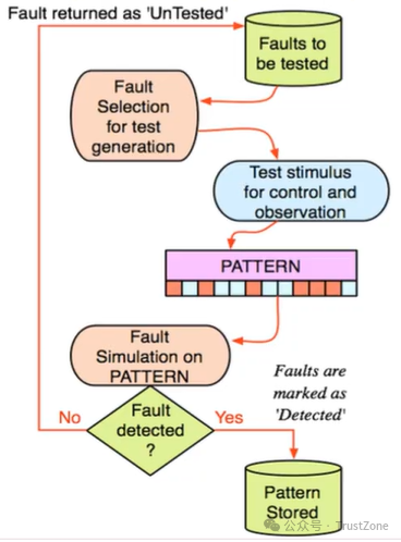
ATPG过程的基本流程是从用户选择的故障集中选择故障。
创建一个模式来控制并观察故障。
对该模式进行故障模拟,以确定正常机器模拟和故障机器模拟之间是否存在差异。
如果目标故障被检测到,则保留该模式。
如果其他故障也恰好被检测到,这些故障也被归类为已检测。
额外的故障模型
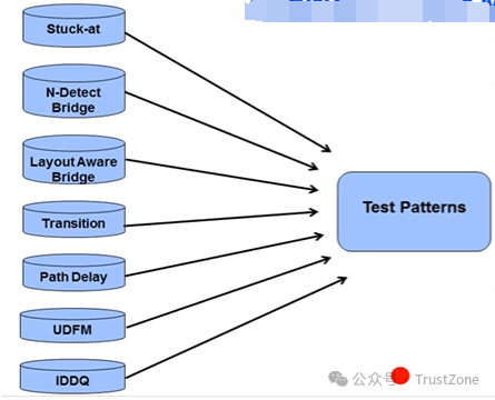
· Stuck-at patterns detect a very largepercentage of all faults
· Transition is next most effective
· Requirements for low DPM typicallydrive the need for additional faultmodels
+ 卡滞模式(Stuck-at patterns)检测出了所有故障中的非常大一部分
+ 转换(Transition)故障模型是接下来最有效的
+ 通常,对低DPM(缺陷每百万机会)的需求推动了对额外故障模型的需求
Layout— Aware Bridge Fault Model
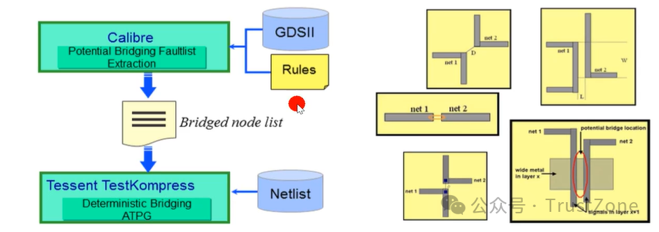
· Limited use-mostly for very high quality requirements.
· Standardized at some companies.
· Deterministic bridge ATPG.
· Layout-aware test targets faults based on physical attributes.
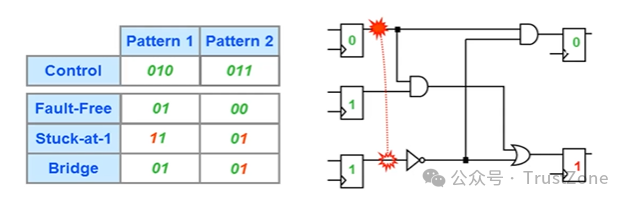
Bridge Fault: Multiple Detection
桥接故障:多重检测
· By default, once a fault is detected, the fault is never targeted for detection again
· For multiple detection , faults are targeted a user specified number of times ("n")
· Each detection increases the statistical chance of detecting a bridge.
The bridge coverage estimate(BCE) reports the ability of multiple detect to statistically detect a bridge defect.
默认情况下,一旦检测到故障,就不会再次针对该故障进行检测。
对于多重检测,故障会被用户指定的次数(“n”)进行检测。
每次检测都会增加检测到桥接故障的统计概率。
桥接覆盖率估计(Bridge Coverage Estimate, BCE)报告了多重检测在统计上检测桥接缺陷的能力。
Bridge Fault:N-Detect
set_multiple_detection -guaranteed_atpg_detections <n>
指定每个可测试故障所需的检测次数
在首次模式生成后,模式生成会继续检测故障第二次、第三次、第四次……直到第n次。
每次检测都需要一个独特的模式来进行控制和观察。这个命令会增加模式的数量。
Bridge Fault: Embedded Multi-Detect
set_multiple_detection -desired_atpg_detections <n>
指定每个可测试故障所需的检测次数
一旦故障被检测到,该故障将被标记为已检测,并尝试进行额外的检测。
嵌入式多重检测(Embedded Multi-Detect,EMD)在故障分级期间向测试立方中添加关注位(care bits),以尝试检测检测次数较少的故障。
这个命令会增加ATPG(自动测试模式生成)的运行时间,但不会增加模式的数量。
At-Speed Fault Models: Transition
Used in more than half of products in industry
Delay fault model:
· Slow-to-rise node.
· Slow-to-fall node
Application of two cycles:
· Launch
· Capture
Detects:
· Partially conducting transistors.
· Resistive bridge defects
在工业中超过一半的产品中使用
延迟故障模型:
· 上升缓慢的节点
· 下降缓慢的节点
两个周期的应用:
· 触发(Launch)
· 捕获(Capture)
可检测:
· 部分导通的晶体管
· 电阻桥接缺陷
At-Speed Fault Models: Path Delay
Limited use-speed binning and silicon trends
Path delay fault model:
· Slow-to-rise path.
· Slow-to-fall path
Application of two cycles:
· Launch
· Capture
Tests for lumped time delay:
· sum of time delays that stack up
· Paths from static timing analysis through a specific path
Detects:
· Partially conducting transistors.
· Diffusions
有限使用——速度分级和硅材料趋势
路径延迟故障模型:
· 上升缓慢的路径
· 下降缓慢的路径
两个周期的应用:
· 触发(Launch)
· 捕获(Capture)
测试集总时间延迟:
· 累加的时间延迟之和
· 从静态时序分析通过特定路径的路径
可检测:
· 部分导通的晶体管
· 扩散层(Diffusions)
User-Defined Fault Models (UDFM)/Cell-Aware UDFM
User-Defined Fault Models (UDFM):
User defined extension to stuck-at and transition faults
Provides a means to specify specific stimulus that must be applied to determine if a fault has been detected.
Cell-Aware UDFM: special application of UDFM
Discussed in-depth in the training module“AdditionalTest Methodologies and Topics".
用户定义的故障模型(UDFM):
用户对卡滞和转换故障的定义扩展
提供了一种指定必须应用的特定激励来确定是否已检测到故障的方法。
单元感知的UDFM:UDFM的特殊应用
在培训模块“额外的测试方法和主题”中进行了深入探讨。
IDDQ Fault Model
前面是针对电压,这个是针对电流的。
Limited use—many chips too noisy for iddq Measures quiescent power supply current during the stable stateTakes time, but attains 80-90% fault coverage
Detects:
· CMos transistor stuck-on/some stuck-open conditions
· Bridging faults
· Partially conducting transistors
有限使用——许多芯片在IDDQ下噪声过大
在稳定状态下测量静态电源电流。
虽然耗时,但能达到80-90%的故障覆盖率
可检测:
· CMOS晶体管卡滞开启/某些卡滞开启条件
· 桥接故障
· 部分导通的晶体管

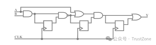
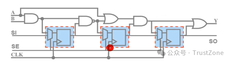
Scan Test
Scan test is a process/flow that:
· Creates control and observation points by replacing flip- flops with scan cells.
· Connects the scan flops together to create scan chains.
· Utilizing these scan chains, test patterns are generated that:
Set a specific value at a specific node. (Control)
Propagate the result so it can be measured. (Observe)
扫描测试是一个过程/流程,它:
· 通过将触发器替换为扫描单元来创建控制和观察点。
· 将扫描触发器连接在一起以创建扫描链。
· 利用这些扫描链,生成测试模式,这些测试模式:
在特定节点上设置特定值(控制)。
传播结果以便可以测量(观察)。
Scan Flip-Flops/Scan Cells
Standard approach today
· Multiplexer selects data input:
D in normal mode.
Scan_in (Sl) scan mode.
· Scan_enable (SE) selects mode of operation.
多路复用器选择数据输入:
· 在正常模式下选择 D。
· 在扫描模式下选择 Scan_in (Sl)。Scan_enable (SE) 选择操作模式。
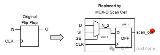
网表阶段是左边的,插入DFT后需要替换成右边的。
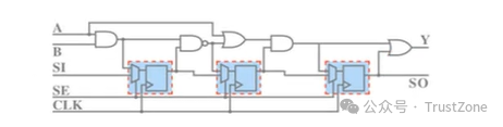
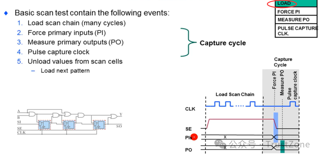
Basic Scan Test -Overview
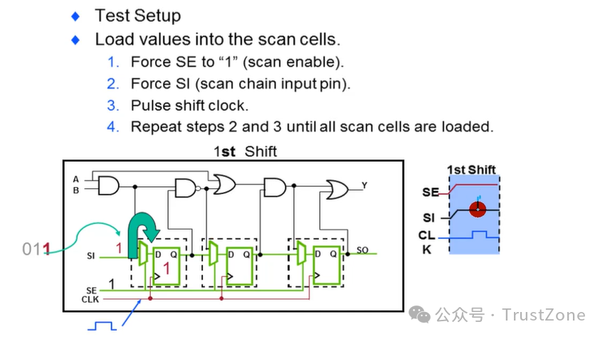
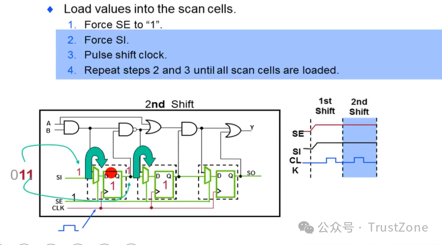
Test setup
Initialize design and set up conditions to enter into test mode (start of test only).
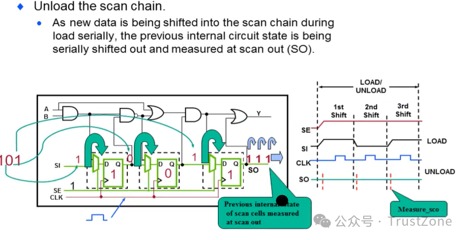
Load/unload-shift
Serially shift known values into scan chain.
Test results are shifted out.
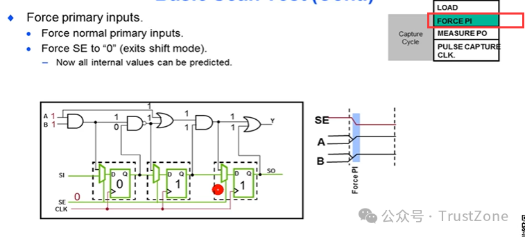
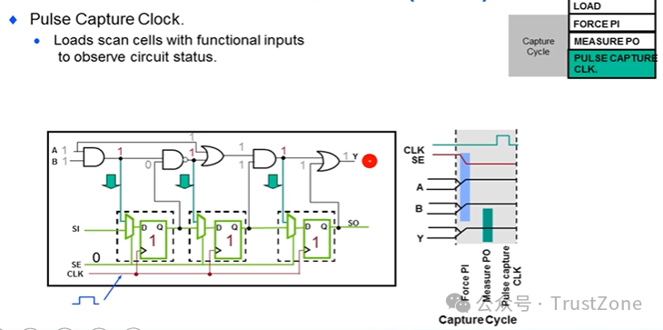
Capture
Apply stimulus defined by known values(Scan and Pl), allow combinational circuitry to operate in functional mode, measure outputs (PO), clock test results into scan chains.
Repeat load/unload
shift/capture until test is done.
测试设置
初始化设计并设置条件以进入测试模式(仅在测试开始时)。
加载/卸载-移位
将已知值串行地移入扫描链。
测试结果被移出。
捕获
应用由已知值(Scan和Pl)定义的激励,允许组合电路在功能模式下运行,测量输出(PO),将测试结果时钟入扫描链。
重复加载/卸载
移位/捕获直到测试完成。
Basic Scan Test
步骤一
step 1
step 2
步骤二
第三步
第四步
第五步
Basic Scan Test Review
Control
· Load scan chains with known values to set internal nodes to a known state.
· Set primary inputs (Pl) to known values
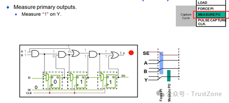
Observe
· As primary outputs (PO) are measured, they are compared to expected values.
· As scan chains are shifted out, they are compared to known values
Pass / Fail
· lf expected values = values from design, test passes.
· lf expected values ≠ values from design, test fails
整个Scan主要的关注点就三点
控制
· 用已知值加载扫描链,将内部节点设置为已知状态。
· 将主要输入(Pl)设置为已知值
观察
· 在测量主要输出(PO)时,将其与预期值进行比较。
· 当扫描链被移出时,它们与已知值进行比较
通过/失败
· 如果预期值 = 设计中的值,则测试通过。
· 如果预期值 ≠ 设计中的值,则测试失败
Tessent Shell
Tessent Shell is a Tcl shell environment that provides a unified Tcl command set and namingconvention.
No extra costs involved.
§ Works with your existing product licenses.
Tessent Shell does the following on your design:
. Tessent FastScan
. Tessent TestKompress
. Tessent Scan
. Tesst Diagnosis
. Tessent MemoryBIST(Shell)
.Tessent LogicBIST(Shell)
.Tessent Scan / ScanPro
. Runs Tessent tools from the Tessent Shell command line.
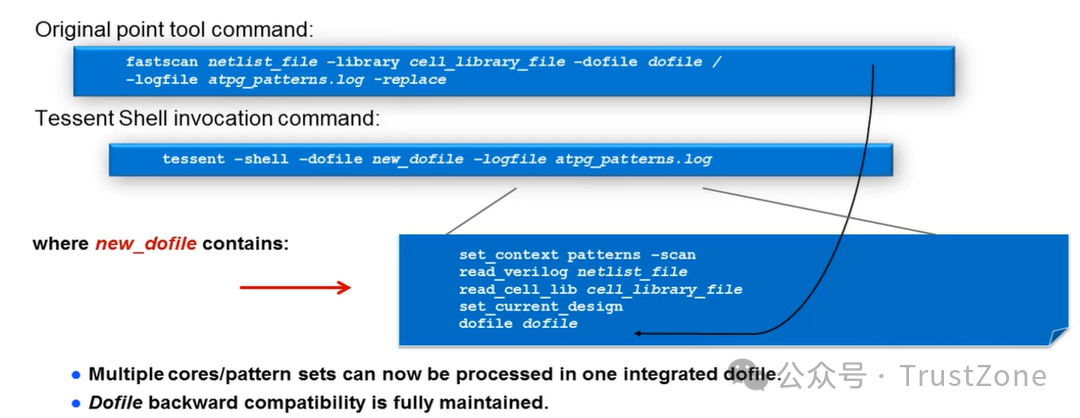
Existing dofiles run in Tessent Shell.
. Minor changes from scripts using point tools when invoking the Tessent Shell and loading design data.
Tessent Shell 是一个 Tcl shell 环境,它提供了一个统一的 Tcl 命令集和命名约定。
不涉及额外费用。
与您现有的产品许可证配合使用。
Tessent Shell 在您的设计上执行以下操作:
. Tessent FastScan
. Tessent TestKompress
. Tessent Scan
. Tessent 诊断
. Tessent MemoryBIST(Shell)
. Tessent LogicBIST(Shell)
. Tessent Scan / ScanPro
. 从 Tessent Shell 命令行运行 Tessent 工具。
现有的 dofiles 可以在 Tessent Shell 中运行。
. 在调用 Tessent Shell 并加载设计数据时,从使用点工具的脚本中进行较小的更改。
Tessent Shell: Contexts and Modes
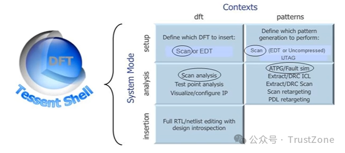
Invocation,System Modes and Contexts
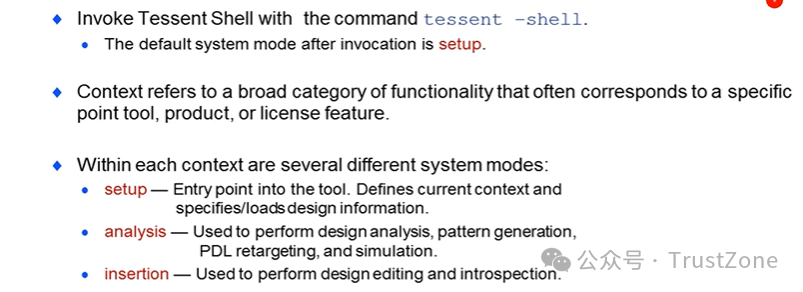 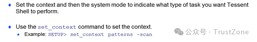
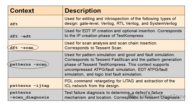
Contexts
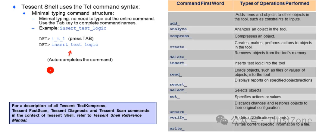
命令语法与结构
调用Tessent Shell内部的FastScan
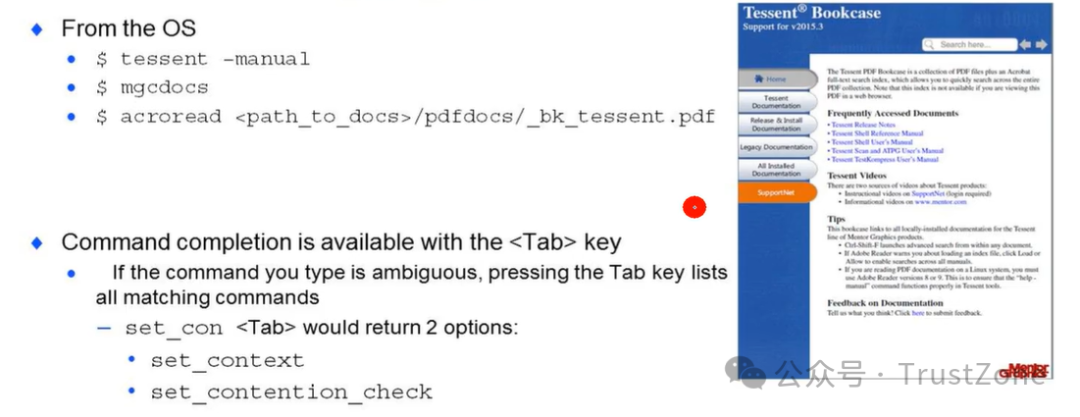
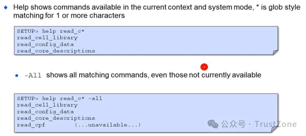
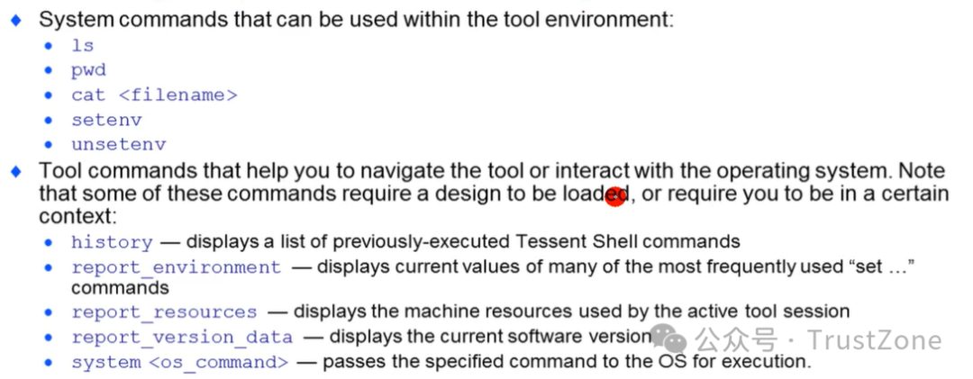
帮助使用Tessent工具
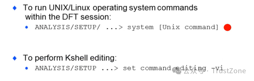
从工具命令行访问UNIX命令
获取帮助:有用的工具和系统命令
小结
Scan test is a structured test that provides control and observe for manufacturing defects
The basic steps for scan test application are:
· Test setup
· Load/unload -shift. Capture
· Load/unload -shift.And so on
Fault models emulate manufacturing defects.
· Basic models include:
· Stuck-at
· User-Defined
· At-Speed
· IDDQ
· Bridging
· Created test patterns are based on fault models in order to detect manufacturing defects.
扫描测试是一种结构化测试,用于控制和检测制造缺陷。
扫描测试应用的基本步骤是:
· 测试设置
· 加载/卸载-移位。捕获
· 加载/卸载-移位。依此类推
故障模型模拟制造缺陷。
· 基本模型包括:
· 固定故障(Stuck-at)
· 用户定义(User-Defined)
· 速度测试(At-Speed)
· IDDQ(静态电流测试)
· 桥接(Bridging)
· 创建的测试模式基于故障模型,以便检测制造缺陷。
碍于时间,很多点并未展开聊聊。以上内容都来自最近我在看的一个课程做的笔记:
点击这里:E课网IC设计学习卡
课程以IC设计公司岗位需求为导向,设立6大方向:设计,验证,后端,DFT,模拟设计,版图!同时还有芯片设计全流程的通用基础入门课!
课程内容配套持续优化:PPT课件、实验手册、作业练习!有需要的同学,同时还可配套VNC账号,理论学习+实操环境数据一次解锁!
拥有了学习卡,不仅可以快速掌握芯片设计的基础通识,还能判断自己是不是适合做芯片设计的工作,单门课程花几天的时间就可以学完,极大提升学习效率!
|